
Understanding Torque and Support Needs for DN200+ Motorized Ball Valves

When a water or process line steps up from DN25 or DN50 into DN200 and above, a motorized valve stops behaving like a small component that can simply be bolted in and forgotten. At that bore size the valve body and its actuator together form a mass hanging on the pipe, and the actuator becomes a load on the electrical distribution as well as on the fluid system.
Three requirements decide whether a DN200+ installation survives commissioning and stays serviceable afterwards. They are not accessories to be value-engineered out at a later stage:
- Independent pipe support. On installations of DN200 or larger, the valve must have pipe support. On DN300 and above, a dedicated pipe support is required specifically to prevent the valve from sagging.
- An upstream protection train. Large-bore lines call for a large strainer, a silent check valve and an expansion joint ahead of the valve, so that debris, reverse flow and thermal movement do not reach the seat.
- A dedicated 220VAC circuit. A high-power actuator needs a dedicated 220VAC supply with an independent breaker — not a spur taken from an existing lighting or control circuit.
This guide works through each requirement using the torque figures and equipment lists that apply across the Tianfei High-Tech large-bore range, then sets out a step-by-step specification sequence for DN200+ projects.
Why DN200 Is the Breakpoint: Problem Definition
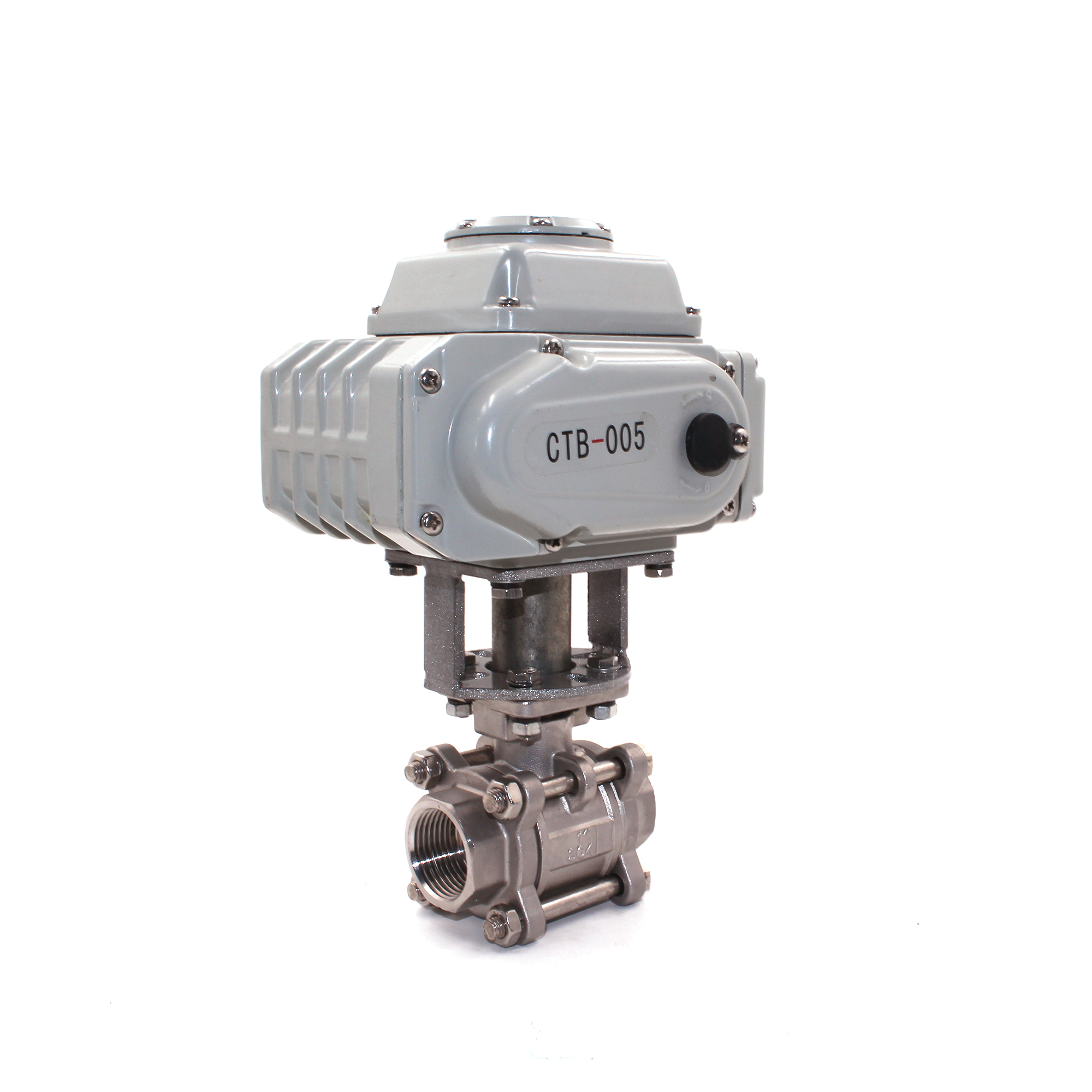
Below DN100, torque is modest enough that the actuator choice rarely drives the piping design. In the Tianfei High-Tech 2-way range, the CWX-15N covers DN15 to DN50 with a 3 N·m motor, the CTB motorized ball valve reaches DN100 with a 6 N·m actuator, and the CWX-60P two-way modulating valve holds a 20 N·m actuator across DN15 to DN100. At those bores a valve can hang on the pipe without anyone worrying about it.
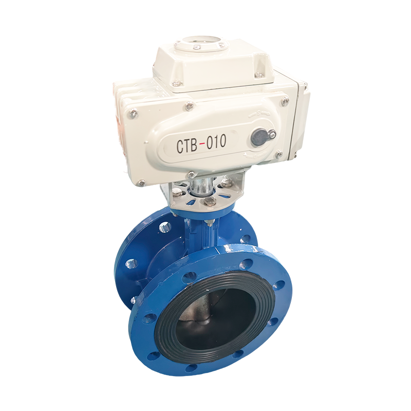
At DN200 the arithmetic changes. The obturator area acted on by the medium is larger, the seating load is larger, and the actuator has to break that seal and drive the full stroke every time. Within the Tianfei High-Tech range, ball-valve bodies are offered up to DN100, and DN200-and-larger pipeline sizes are served by the CTB motorized butterfly-valve platform: a wafer-type body from DN50 to DN300 with adaptive torque from 20 to 200 N·m, and a flanged body from DN50 to DN500 with torque from 30 to 500 N·m.

Weight scales with bore as well, and weight is what turns a valve into a structural problem. A DN200-plus body with a high-torque actuator, clamped between flanges, creates a bending moment at the pipe connection. Without a support underneath, the assembly can settle, the stem alignment drifts, and the seat no longer seals concentrically. The actuator then has to overcome the added friction it created, which shortens its service life and increases current draw.
Three further conditions amplify the mechanical problem at large bore:
- Debris. A large-bore main collects more solids than a small branch. If a foreign object wedges between the disc and the seat, the actuator is asked to force the obturator against an obstruction rather than against fluid. A large strainer upstream removes the cause.
- Reverse flow and water hammer. The volume of water moving in a DN200+ line produces a significant momentum change when flow reverses. A silent check valve in the train limits that effect before it reaches the valve.
- Thermal movement. Long, large-diameter runs expand and contract more than short ones. An expansion joint absorbs that movement so the valve body is not asked to act as an anchor.
Finally, the electrical side stops being trivial. A high-power actuator draws materially more current than the small DN15 to DN50 actuators used on residential and light commercial lines, which is why a dedicated 220VAC circuit with an independent breaker is specified rather than shared wiring.
Industry Background: Where Large-Bore Motorized Valves Sit in 2026
The commercial context matters because it explains why DN200+ specification practice is tightening rather than loosening. According to Dataintelo, the global motorized ball valve market was valued at USD 8.7 billion in 2025 and is projected to reach USD 14.2 billion by 2034, with Asia Pacific holding a 38.5% revenue share in 2025. The Insight Partners projects the IoT valve market to reach USD 2.85 billion by 2031, growing at a CAGR of 10.4% from 2023. Within the valve market, two-way motorized ball valves hold the largest segment share at 42.1%, according to Dataintelo.
Supply concentration is equally relevant. OEC data shows China exported USD 22.6 billion in total valves in 2024, maintaining a 20% global export share. Buyers sourcing large-bore motorized valves from Chinese manufacturers are therefore working inside a deeply established export sector rather than an emerging one.
Regulatory pressure adds a second dimension. Motorized valves entering the EU market must comply with CE marking under EN 60335-1 and with RoHS 2.0 under IEC 62321. For municipal and potable-water projects, that baseline is frequently extended by drinking-water approvals at the project level.
Reading market size figures carefully. Published valuations diverge because the boundaries of the category differ. For the same nominal period, Dataintelo reports USD 8.7 billion for the motorized segment, Market Research Future reports USD 13.8 billion for ball valves generally, and Global Market Insights reports USD 12.6 billion. The gap is definitional, not a contradiction — which is why a specification decision should rest on the bore, torque and support data rather than on a headline number.
Tianjin Tianfei High-tech Co. is one of the manufacturers operating in this segment. Established on March 16, 2009, and headquartered in Tianjin, the company is a national high-tech enterprise under Tianjin Jinfeng Technology Investment Group and a founding member of China's micro electric valve industry, specializing in the R&D, manufacturing and sales of high-end intelligent valves and metering instruments. Its annual output capacity is 1,000,000 units, roughly 70% of production is exported, and its main markets are Europe and America, South America, Central America, Southeast Asia and East Asia. Its verified production capacity stands at 30,000 m² with an annual output capability of 1,000,000 units.
The Solution Set: How the Large-Bore Range Meets These Requirements
Torque coverage from DN15 to DN500
Torque is the first specification decision, because it determines actuator size, current draw and the physical envelope the piping must accommodate. In the CTB motorized butterfly range, the wafer-type body delivers adaptive torque from 20 to 200 N·m across DN50 to DN300, while the flanged body delivers 30 to 500 N·m across DN50 to DN500, with the 500 N·m figure sized for DN500 service. Both platforms use an offset-shaft geometry — triple eccentric on the wafer body, double eccentric on the flanged body — to reduce running torque, which in turn reduces motor load and energy consumption.
The same torque-density logic appears lower down the range and is worth understanding before sizing a large valve. The CWX-25S drives DN80 with 10 N·m and does not need a gear reducer. The CWX-60P two-way valve holds DN100 with a 20 N·m actuator. A buyer who has only worked with DN15 to DN50 valves often over-specifies torque on the first large-bore project; the correct approach is to match the torque class to the bore and the eccentric design rather than to add margin by default.
Pipe support at DN200+ and DN300+
This is the requirement most often missed at the drawing stage. The equipment list for the wafer-type CTB motorized butterfly valve states plainly that pipe support is required on DN200-and-larger installations. The flanged CTB list goes further: on DN300 and above, a dedicated pipe support is required to prevent the valve from sagging.
In practice this means the support must be designed into the piping layout at the outset, so that installation crews do not use the valve as a convenient hanging point for the adjacent pipe run. The support carries the valve plus actuator mass; the pipe carries the fluid. When that division of labour is respected, the concentricity of stem and seat is preserved and the actuator runs within its rated torque envelope for the life of the installation.
The upstream protection train
The upstream equipment list differs by body type, and the difference is deliberate:
| Position in the train | Wafer-type CTB motorized butterfly valve | Flanged CTB motorized butterfly valve |
|---|---|---|
| Upstream | Large strainer, silent check valve, expansion joint | Large Y-strainer, isolation gate valve, expansion joint |
| Downstream | Flow meter, pressure transmitter | Large electromagnetic or ultrasonic flow meter, silent slow-closing check valve |
| Piping interface | Wafer installation, clamped between flanges, no independent flanges | Companion flanges, pressure-rated gaskets (rubber / NBR / EPDM), high-strength bolts |
| Control interface | PLC with 4-20mA signal, SCADA, remote RTU | SCADA remote monitoring, PLC interlock |
Each upstream item does a specific job. The large strainer keeps solids off the seat. The silent check valve limits reverse flow and the pressure surge that follows it. The expansion joint absorbs axial and lateral pipe movement so the valve body is not loaded by thermal expansion. On the flanged installation, an isolation gate valve is added so the motorized valve can be taken out of service without draining the whole line, and the downstream silent slow-closing check valve provides a second, gentler surge control point.
Electrical supply, control and signal integrity
The electrical requirement is stated directly in the equipment list: a high-power actuator needs a dedicated 220VAC circuit, and an independent breaker is recommended. This is a fundamental change from small-bore practice, where a DN15 to DN50 actuator can often share a circuit with other building services. A large-bore actuator that trips a shared breaker takes unrelated equipment down with it.
Voltage options across the CTB range are AC220V and DC24V, with IP67 protection and a working pressure rating of ≤1.6MPa, so the enclosure is rated for wet and splash-exposed locations such as pits and plant rooms. For modulating duty, the signal path needs the same care as the power path: the two-way modulating line uses shielded twisted pair cable (RVVP 2×1.0mm²) for analogue anti-interference, powered from an independent 24VDC module so the signal is isolated from the supply. On large-bore modulating installations, a control signal that drifts because of induced noise is read by the DDC or PLC as a genuine flow demand, and the valve hunts.
Where feedback is needed, the flanged large-bore platform provides a visual position indicator together with limit switch electrical confirmation, giving operators both a local and a remote view of valve state.
Materials, seats and sealing
Large-bore valves are exposed to more aggressive service than small ones, because the lines they sit on usually run continuously. The CTB platform uses cast iron or SS304 bodies, with replaceable seats available in EPDM, NBR or VITON so that the seat compound can be matched to media temperature and chemistry without changing the valve body. The flanged body receives anti-seawater electrochemical corrosion treatment, allowing direct use in ship seawater piping. Pressure ratings cover PN6, PN10 and PN16, spanning low-pressure water through to medium-pressure industrial duty, and the wafer body carries an anti-corrosion coated (epoxy powder) finish intended for buried and wet environments.
Step-by-Step: Specifying a DN200+ Motorized Valve Installation
- Confirm bore and pressure class. Fix the nominal bore and the pressure rating first (PN6, PN10 or PN16 on the flanged platform). Bore and pressure class together determine whether the wafer or flanged body applies, and they set the torque starting point.
- Set the torque envelope. For DN50 to DN300, the wafer platform offers adaptive torque from 20 to 200 N·m; for DN50 to DN500 the flanged platform offers 30 to 500 N·m. Factor in the eccentric geometry — triple eccentric on wafer, double eccentric on flanged — because it reduces running torque and therefore the motor load the electrical design has to support.
- Choose the installation interface. Wafer installation clamps between existing flanges with no independent flanges and saves space and installation time compared with a flanged butterfly valve. Flanged installation requires companion flanges, pressure-rated gaskets in rubber, NBR or EPDM, and high-strength bolts, but is easier to inspect and remove. Above DN300 the flanged platform is the applicable choice.
- Build the upstream protection train. Wafer: large strainer, silent check valve, expansion joint. Flanged: large Y-strainer, isolation gate valve, expansion joint. Confirm the downstream side as well — flow meter and pressure transmitter on the wafer line; large electromagnetic or ultrasonic flow meter and silent slow-closing check valve on the flanged line.
- Design the pipe support. This is a mandatory item, not an option. DN200 and larger requires pipe support under the valve assembly; DN300 and larger requires a dedicated support to prevent sagging. Place the support so that it carries the valve and actuator mass independently of the adjacent pipe run.
- Provision the electrical supply. Run a dedicated 220VAC circuit to the high-power actuator and protect it with an independent breaker. For modulating duty, add an isolated 24VDC supply module and shielded twisted pair cable to the controller.
- Configure control and verify feedback. Wire the actuator to the PLC, SCADA or remote RTU as specified — 4-20mA on the wafer line, SCADA monitoring with PLC interlock on the flanged line. Confirm the limit switch and visual position indicator agree before the line is pressurised.
Use Cases: Where DN200+ Requirements Actually Bite
The DN200+ rule set is not theoretical. It applies wherever bore size puts meaningful mass and torque into a single assembly:
- Municipal water supply and drainage. Trunk mains, treatment plant inlet and outlet lines, and district metering points.
- Wastewater treatment. Large-bore isolation on sludge and process lines, where debris makes upstream straining critical.
- Power plant cooling water. Circulating water lines where modulating control and valve position feedback are both required.
- Marine and seawater systems. Ship seawater piping, where the anti-seawater electrochemical corrosion treatment on the flanged body is directly relevant.
- Large-bore HVAC and fire protection. Plant room headers and riser isolation where the valve must be inspectable and manually operable.
- Industrial process piping. Chemical, petroleum and pharmaceutical lines where the seat compound and the pharmaceutical-grade environment requirements drive the specification.
Case reference — municipal water, France. A large European municipal water group inspected the Tianjin Tianfei High-tech factory in October 2024 and approved the production and quality-control system. A 10,000-unit order was signed in November 2024 for on/off control and flow regulation across municipal water supply and drainage networks, sewage treatment plants and smart water automation systems, and was delivered within three months. Reported results after more than sixteen months of stable operation: 4-20mA regulation with a response time of ≤0.5 seconds and flow control error below ±2%; zero leakage and zero major failures; remote monitoring, fault diagnosis and automatic alarm reducing maintenance cost by 40%; and a low-power design saving more than 120,000 kWh of electricity annually. The project was delivered at 25% lower price and 40% shorter delivery time than the international peers evaluated in the same tender. Equipment on that project came from the CTB flanged valve, CTB motorized ball valve and CTB motorized butterfly valve families.
Comparison: Wafer vs Flanged Large-Bore Motorized Valves
Both platforms cover DN200 and above, so the choice between them is an installation and maintenance decision rather than a capability decision. The table below uses only published specifications from the two product families.
| Parameter | CTB wafer-type motorized butterfly valve | CTB flanged motorized butterfly valve |
|---|---|---|
| Bore range | DN50 – DN300 | DN50 – DN500 |
| Actuator torque | 20 – 200 N·m (adaptive) | 30 – 500 N·m |
| Disc / shaft design | Triple eccentric disc (offset shaft, offset seal, offset rotation) | Double eccentric design for low torque |
| Installation interface | Wafer, clamped between flanges, no independent flanges | Flanged, PN6 / PN10 / PN16 |
| Upstream equipment | Large strainer, silent check valve, expansion joint | Large Y-strainer, isolation gate valve, expansion joint |
| Downstream equipment | Flow meter, pressure transmitter | Large electromagnetic or ultrasonic flow meter, silent slow-closing check valve |
| Pipe support requirement | Pipe support required at DN200 and above | Dedicated pipe support required at DN300 and above to prevent sagging |
| Body material and protection | Cast iron / SS304; anti-corrosion epoxy powder coated body for buried and wet environments | Cast iron / SS304; anti-seawater electrochemical corrosion treatment |
| Seat options | Replaceable seat — EPDM / NBR / VITON | Replaceable seat — EPDM / NBR / VITON |
| Voltage and IP rating | AC220V / DC24V, IP67 | AC220V / DC24V, IP67 |
| Working pressure | ≤1.6MPa | ≤1.6MPa |
| Control interface | On/Off & Modulating (4-20mA); PLC, SCADA, remote RTU | SCADA remote monitoring, PLC interlock |
For projects that need to select an actuator torque class before the piping layout is frozen, the reference table below shows how torque scales with bore across the full Tianfei High-tech motorized range.
| Model | Bore range | Actuator torque | Voltage |
|---|---|---|---|
| CWX-15N motorized ball valve | DN15 – DN50 | 3 N·m | AC220V / DC12V / DC24V |
| CWX-20P motorized ball valve | DN20 – DN50 | 5 N·m | AC220V / DC24V |
| CTB motorized ball valve | DN15 – DN100 | 6 N·m | AC220V / DC24V |
| CWX-25S motorized ball valve | DN25 – DN80 | 10 N·m | AC220V / DC24V |
| CWX-60P 2-way motorized ball valve | DN15 – DN100 | 20 N·m | AC220V / DC24V |
| CWX-60P 3-way motorized ball valve | DN15 – DN50 | 20 N·m | AC220V / DC24V |
| CTB wafer-type motorized butterfly valve | DN50 – DN300 | 20 – 200 N·m | AC220V / DC24V |
| CTB flanged motorized butterfly valve | DN50 – DN500 | 30 – 500 N·m | AC220V / DC24V |

Frequently Asked Questions
What certification and standards requirements apply to DN200+ motorized valves supplied into the EU?
Motorized valves placed on the EU market must comply with CE marking under EN 60335-1 and with RoHS 2.0 under IEC 62321. That is the mandatory baseline. Municipal and potable-water projects usually add a project-level drinking-water approval on top: the CTB motorized ball valve is available in a version compliant with municipal water certification, with WRAS or FDA certified versions optionally available. Because certification records are model-specific, the version and seat material should be confirmed for the exact large-bore model being ordered rather than for the product family as a whole.
How much torque does a DN200 to DN300 motorized valve need, and does it always require pipe support?
In the Tianfei High-tech large-bore range, the wafer-type CTB motorized butterfly valve covers DN50 to DN300 with adaptive torque from 20 to 200 N·m, and the flanged CTB covers DN50 to DN500 with 30 to 500 N·m. Pipe support on DN200-and-larger installations is mandatory, and at DN300 and above a dedicated pipe support is required specifically to prevent the valve from sagging. High-power actuators in this class also need a dedicated 220VAC circuit with an independently rated breaker. The triple eccentric disc on the wafer body and the double eccentric design on the flanged body reduce running torque, which lowers both motor load and energy consumption.
What drives the cost of a DN200+ motorized valve package?
Cost is driven by body material (cast iron versus SS304), seat compound (EPDM, NBR or VITON), actuator torque class, IP rating (IP67 across the CTB range), control mode (on/off versus 4-20mA modulating), and the certification version required. Critically, the pipe support, large strainer, silent check valve and expansion joint are separate line items and should be budgeted alongside the valve itself — at DN200+ they are not optional accessories. For reference, in the French municipal water project commissioned in November 2024, the delivered package came in at 25% lower price and 40% shorter delivery time than the international peers evaluated in that tender.
Can a sample be supplied before a DN200+ order is placed?
Yes. The standard minimum order quantity is 2 units, OEM customization of voltage and logo is available, and quality control is 100% testing across production. After-sales service is provided remotely for commissioning and troubleshooting. For large-bore projects it is worth validating three things at sample stage: the torque class against the actual bore, the seat compound against the media, and the actuator control mode against the control system that will drive it.
What lead time and capacity should a DN200+ project plan around?
Standard lead time is 30 days, supported by a monthly capacity of 8,000 units and an annual output capacity of 1,000,000 units. In the French municipal water project, a 10,000-unit order signed in November 2024 was delivered within three months, which was 40% shorter than the peer benchmark in the same tender. For DN200+ projects the practical planning point is sequencing: the pipe support and the upstream protection train should be procured in parallel with valve production so that the support structure is ready when the valve arrives on site. To discuss a specific large-bore configuration, contact Mrs Wang at tf.co@tfjt.com or +86 022 85685296, or via WhatsApp on +86 18920338351.
Conclusion
At DN200 and above, three parameters decide whether a motorized valve installation performs as designed. Torque has to match the bore and the eccentric disc design — 20 to 200 N·m across DN50 to DN300 on the wafer platform, 30 to 500 N·m across DN50 to DN500 on the flanged platform. Pipe support is mandatory at DN200 and larger, and becomes a dedicated support at DN300 and above to prevent sagging. And the high-power actuator needs its own dedicated 220VAC circuit with an independent breaker, plus a clean signal path if the valve is modulating.
Wrap those three requirements around the upstream protection train — large strainer, silent check valve, expansion joint — and the installation addresses the failure modes that large-bore projects actually encounter: seat damage from debris, surge damage from reverse flow, distortion from thermal movement, and actuator overload caused by an unsupported valve body.
Next Step: Specify Your DN200+ Configuration
Tianjin Tianfei High-tech Co. manufactures the CTB large-bore motorized valve platform from a 30,000 m² production base with an annual output capacity of 1,000,000 units, and provides OEM voltage and logo customization with 30-day standard lead times and 100% unit testing.
Send your bore size, pressure class and control mode for a configuration review and quotation.
Email: tf.co@tfjt.com | Tel: +86 022 85685296 | WhatsApp: +86 18920338351
Website: www.minimotorizedvalve.com
Specification figures in this article refer to the Tianfei High-tech CWX and CTB motorized valve families. Market and export figures are attributed to Dataintelo, The Insight Partners and OEC as cited. Installation requirements stated for DN200+ and DN300+ pipe support, upstream protection equipment and dedicated 220VAC supply refer to the CTB large-bore motorized butterfly valve platforms.
Have Questions or Need More Details?
Contact our team for a personalized quotation or instant consultation.
Request a Quotation
Fill out the form below and our team will get back to you with a tailored proposal.
WhatsApp Direct Chat
Prefer to chat in real-time? Message us on WhatsApp for instant assistance & quick answers.
- Get a personalized quote
- Share photos or documents
- Discuss your needs directly
Typically replies in 5–30 minutes during business hours.