
Wireless vs. Wired vs. Mechanical: Choosing a Motorized Ball Valve for Automatic Shutoff
Short answer: there is no universally correct shutoff architecture. The right choice is set by three constraints that rarely occur together: whether mains power is available at the pipe, how quickly the valve must close after detection, and who needs to see the alarm. A WiFi 2.4GHz battery valve fits homes, rentals and garden irrigation; a wired conductive-sensing system fits data centers, electrical rooms and hotel or hospital floor monitoring; a self-acting mechanical temperature control valve fits hot-water loops where no power or controller exists at all.
This guide compares the three on five verifiable criteria — power source, response time, integration ecosystem, sensor cable reach, and the supporting equipment each one demands — then converts the comparison into a 'choose this if' matrix by application.
What 'automatic shutoff' actually requires
An automatic shutoff system has three layers: a sensor that detects water or an out-of-range temperature, a decision layer that converts that signal into a command, and an actuator that physically closes the valve. A motorized ball valve is the actuation layer. It is not a detector, and it is not a monitoring platform.
Most failed projects fail in one of three predictable places. First, power: a valve specified without a defined supply has no way to close. Second, response: a system that closes 'eventually' is measured in minutes rather than seconds, which changes the damage profile. Third, alarm visibility: a valve that closes silently protects the pipe but not the building manager, who then has no idea which floor triggered the event.
Defining these three layers before comparing hardware prevents the most expensive mistake in this category — buying a valve that is technically correct but architecturally unreachable.
Industry background: why the decision sits in the automation layer
The ball valve category overall is large and mature. Straits Research valued the global ball valve market at USD 14.8 billion in 2025, with a projection of USD 22.82 billion by 2034. The component layer that turns a manual valve into an automatic one is growing faster: Dataintelo reports the global electric valve actuators market at USD 4.8 billion in 2025 with a CAGR of 5.8%.
Two practical consequences follow for buyers and specifiers. First, the differentiation between suppliers increasingly sits in the actuator, the control interface and the detection logic rather than in the valve body alone. Second, tariffs and customs classification now matter to the specification: motorized valves with self-contained electric or hydraulic actuators are classified under HS Code 848180, so the actuator choice can affect both the landed cost and the import documentation.
The comparison below therefore treats each architecture as a complete system — valve, power, detection and signal path — rather than as a single part number.
The five criteria that decide the architecture
| Criterion | WiFi 2.4GHz smart valve | Wired conductive-sensing system | Self-acting mechanical valve |
|---|---|---|---|
| Power source | DC6V (4 × AA batteries) or DC5V USB, with automatic switch to the USB supply | DC12V or DC24V from a system power supply | None — liquid-filled bulb, self-operated |
| Detection logic | In-app leak protection: paired leak sensor trips, valve closes, push alarm is sent | Conductive sensing electrodes; N.O./N.C. relay output | Temperature only; no leak detection function |
| Response time | Commanded from the app or by a sensor-triggered rule | Detection response under 3 seconds, then relay signal to BMS/DCS | Continuous modulating action, ±1°C accuracy |
| Integration ecosystem | WiFi 2.4GHz (IEEE 802.11b/g/n); Tuya Smart, SmartLife, Alexa, Google Home | Dry contact to BMS/DCS; units are cascadable along the sensing run | None — no controller, no network, no remote status |
| Sensor cable reach | 1 m cable supplied with the wireless leak sensor | Standard 1 m, extendable to a maximum of 50 m | Bulb sensing at the valve body; no cable run |
| Ingress protection | Valve IP54; wireless sensor IP44 | Sensor IP44 | Brass body, no electrical enclosure |
Option A — WiFi 2.4GHz smart valve: battery-powered closure with app control

SMT workshop: the control electronics that sit inside a WiFi smart water valve are produced in-house.
The WiFi Smart Water Valve is a wireless motorized ball valve built on a stainless steel (SS304) body in sizes DN15 to DN25 — the residential bore range that covers a house main, a riser to a rental unit, or a garden irrigation line. It communicates on WiFi 2.4GHz (IEEE 802.11b/g/n) and runs on the Tuya Smart and SmartLife platforms with Alexa and Google Home voice control. The valve body is rated IP54 and the paired wireless leak sensor IP44.
Power is the defining feature. The actuator accepts DC6V from four AA batteries or DC5V over USB, and switches to the USB supply when it is connected. That design decision removes the need for an electrician at the installation point — a genuine advantage in finished apartments and rental units where pulling a new circuit is disproportionate to the job. Where the application depends on long battery intervals, confirm the standby figure for the actual switching frequency at quotation stage; in the same product family, the wireless water leak sensor is specified with 3 × AAA batteries and a standby time of more than one year.
Leak protection is handled in the app rather than in a control panel: when a paired sensor detects water, the valve closes and a push alarm reaches the phone. This is the architecture's main strength and its main limit. It protects the property when someone is reachable and the 2.4GHz network is up; it is not a substitute for a supervised BMS alarm in a facility with a duty engineer.
Option B — Wired conductive sensing: relay output and sub-3-second detection
The Wired WLD wired water leak sensor operates on DC12V or DC24V, detects water by conductive sensing, and reports through a N.O./N.C. dry-contact relay that connects directly to a BMS or DCS. Its detection response is under 3 seconds. The sensor cable is 1 m as standard and can be extended to a maximum of 50 m, and units cascade along the run — which is what makes it viable for a data hall subfloor, a switch room, or a hotel floor where one cable must cover several risk points and one alarm must appear on a single supervisory screen.
A lighter variant in the same logic is the WATER LEAK ALARM VALVE (WLAV): DC12V, conductive sensing, DN15 to DN25, a buzzer plus relay dry contact, a 1–5 m sensor cable and IP44 protection. It suits single-room protection — a kitchen, a bathroom, an office riser — where a local audible alarm is sufficient and no supervisory system exists.
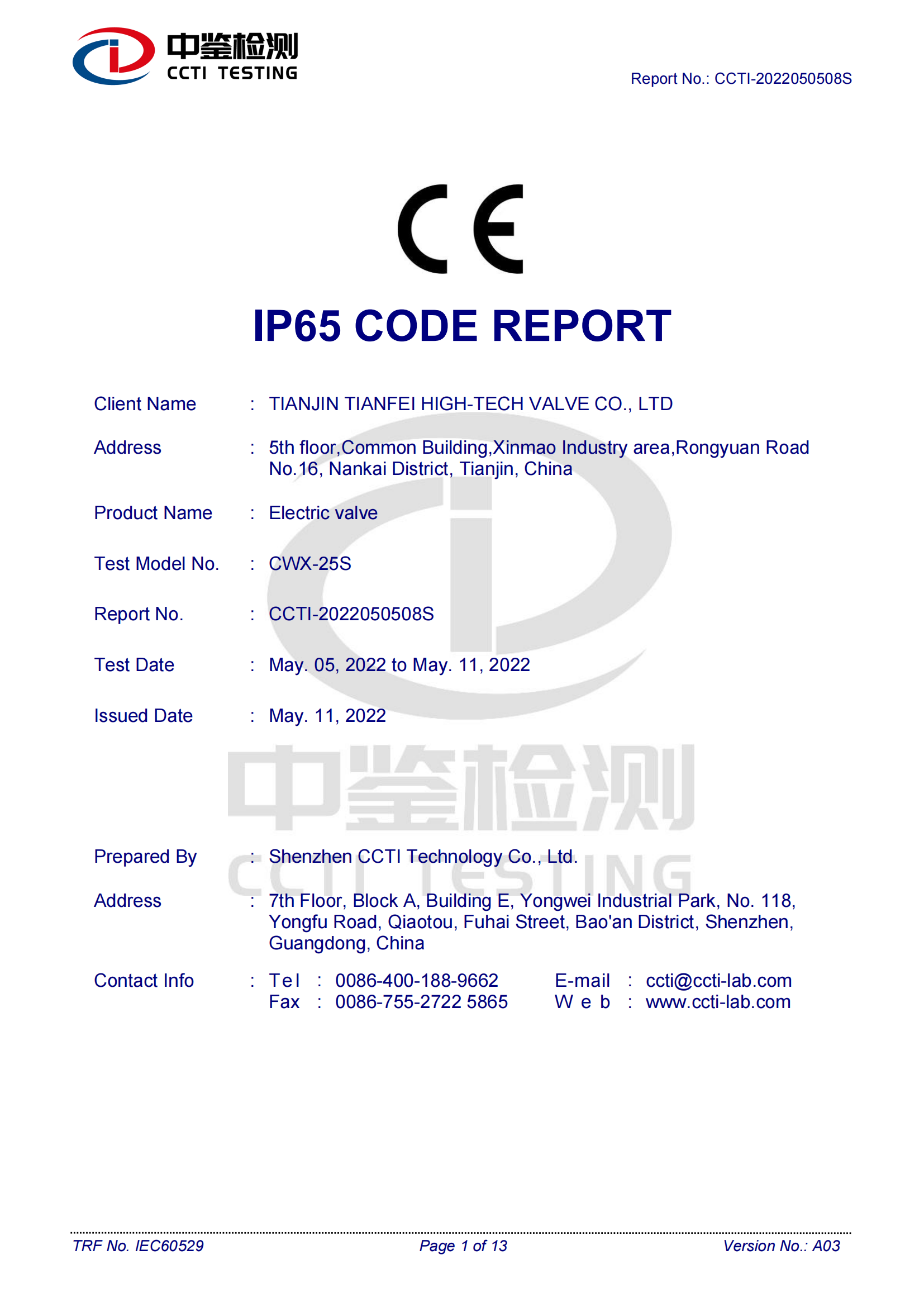
IP65 code report issued by CCTI Testing to IEC 60529, certificate CCTI-2022050508S, covering the CWX-25S electric valve. Enclosure ratings should always be read against the exact model and certificate scope, not against a product family.
The trade-off is installation. A wired system needs a DC supply, a cable route and a defined point of connection to the supervisory system, and its sensors are IP44 — appropriate for indoor subfloor and plant-room monitoring, not for washdown or outdoor exposure. In exchange, it delivers the two things a facility specification usually demands: a hard-wired signal and a response measured in seconds.
Option C — Mechanical self-acting valve: no power, no controller, no signal
The Temperature Control Valve (TCV) is a self-operated thermostatic valve driven by a liquid-filled bulb. It requires no electrical supply and no controller, which makes it unaffected by power loss — a meaningful property in a stairwell, a remote riser or a plant room where a nuisance trip should not leave a loop uncontrolled. It covers DN15 to DN32, working pressure up to 1.0 MPa, a temperature range of 20–80°C, and holds ±1°C accuracy on hot or cold water in a brass body. Typical duty is floor heating control, radiator control, solar hot water and industrial temperature regulation.
Its limitation is categorical rather than technical: a mechanical self-acting valve regulates temperature. It does not detect water, it does not send an alarm, and it cannot be told to close from a phone or a BMS. Selecting it for leak protection would be a specification error, not a product failure.
Supporting equipment: what each architecture drags into the bill of materials
The valve is rarely the only line item. A complete shutoff installation usually includes an isolation valve upstream of the assembly, a pipe strainer to keep debris out of the ball and seat, a silent check valve to prevent backflow, and an expansion joint to absorb thermal movement and protect the actuator from pipe stress. High-torque AC actuators are normally fed from a dedicated 220VAC circuit rather than tapped from a lighting loop — a planning item that determines both cable sizing and who signs off the electrical installation.
Pipe support deserves separate attention because it is the most commonly under-specified item on larger bores. From DN200 upward, the weight of a filled valve body and the reaction torque of the actuator should be carried by independent pipe supports, not by the valve flanges. In this portfolio the ball valve bodies run to DN100 (the CWX-60P and CTB series), so shutoff duty above that moves to a butterfly valve body — the CTB flange pattern covers DN50 to DN500 with 30–500 N·m torque, and the wafer pattern covers DN50 to DN300 with 20–200 N·m torque, both rated IP67 and ≤1.6 MPa. Larger, heavier bodies are precisely where support design stops being optional.
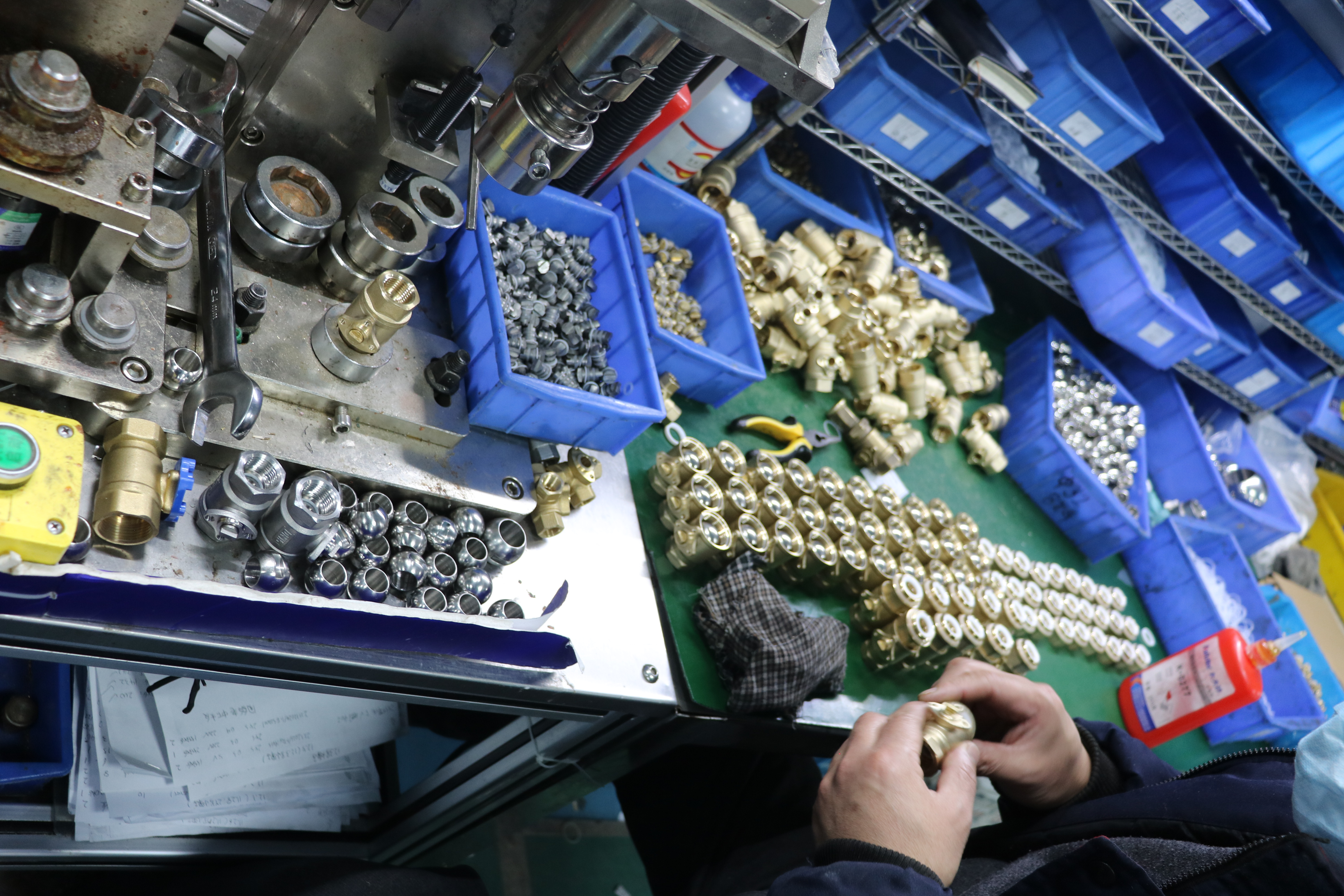
Destructive testing during production: shutoff performance depends on seat and body integrity, not only on the actuator.
Step-by-step: specifying a shutoff architecture in eight steps
- Define the failure mode first. Decide whether the risk is water escaping a pipe (leak detection) or a loop drifting out of temperature (regulation). The two answers lead to different product families and cannot be merged into one device.
- Audit power at the installation point. If a DC supply is already present, wired sensing is available. If not, decide between running a circuit and using a battery valve.
- Convert the risk into a response requirement. A sub-3-second detection response with a relay output is a facility requirement; an app push alarm is a property-management requirement. Both are legitimate; they are not interchangeable.
- Map the sensor cable route. Standard 1 m is enough for a single point. A cable run up to 50 m with cascaded units covers a data hall subfloor — but the route must be designed, not improvised on site.
- Choose the integration end point. Tuya Smart, SmartLife, Alexa or Google Home for residential control; N.O./N.C. dry contact into BMS/DCS for facility control; no integration at all for a self-acting valve.
- Fix valve size, body material and control mode. Match bore to the pipe (DN15–DN25 for the WiFi valve, DN20–DN50 for the CWX-20P, DN15–DN100 for the CWX-60P and CTB), confirm normally-closed or normally-open logic, and remember that a 3-way motorized ball valve with T or L port is for mixing and diverting duty, not for simple shutoff.
- Specify voltage for the destination market. Commercial catalogues list 24V AC, 24V DC, 120V AC and 240V AC options, while this portfolio covers AC220V, AC85–265V, DC12V, DC24V and DC9–24V. Buyers in 120V regions should state the requirement at RFQ stage; voltage and logo customization are available as OEM options.
- Design the mechanical support. Add strainer, check valve, expansion joint and, from DN200 upward, independent pipe supports sized for the filled valve weight plus actuator torque.
Decision matrix: choose this if…
| Application | Choose | Because |
|---|---|---|
| Home or rental leak protection | WiFi Smart Water Valve (DN15–DN25) plus wireless leak sensor | No new circuit required; battery or USB power; closes and pushes an alarm to the occupant or landlord |
| Smart home water control | WiFi Smart Water Valve | Native Tuya Smart / SmartLife operation with Alexa and Google Home voice control |
| Garden irrigation | WiFi Smart Water Valve (IP54) or CWX-20P for larger lines | Scheduled open/close from the app; CWX-20P extends coverage to DN20–DN50 with 5 N·m torque |
| Server room subfloor | Wired WLD with cascaded sensors | Under 3-second detection response, cable up to 50 m, N.O./N.C. relay into BMS/DCS |
| Kitchen or bathroom pipe monitoring | WLAV, or WiFi valve plus wireless sensor | WLAV gives a local buzzer and relay contact on a 1–5 m cable; the WiFi option gives remote notification without wiring |
| Hotel or hospital floor monitoring | Wired WLD on each monitored floor | One supervisory signal per floor, cascadable sensors, no reliance on staff phones |
| Floor heating, radiators, solar hot water | TCV self-acting valve | ±1°C control across 20–80°C with no power or controller, unaffected by power loss |
Specification comparison of representative models
| Model | Type | Power | Size | Protection |
|---|---|---|---|---|
| WIFI WATER VALVE | WiFi wireless motorized ball valve, SS304 | DC6V (4 × AA) / DC5V USB | DN15–DN25 | IP54 |
| Wired WLD | Wired water leak sensor, N.O./N.C. relay | DC12V / DC24V | Cable 1 m, max. 50 m | IP44 |
| WLAV | Linked alarm shut-off valve, buzzer + dry contact | DC12V | DN15–DN25; cable 1–5 m | IP44 |
| TCV | Self-operated thermostatic valve, liquid-filled bulb | None | DN15–DN32, 20–80°C, ±1°C | Brass body, ≤1.0 MPa |
| CWX-15N | 2-way motorized ball valve, normally closed/open/hold | AC220V / DC12V / DC24V | DN15–DN50, 3 N·m | IP65 |
| CWX-20P | 2-way motorized ball valve, brass | AC220V / DC24V | DN20–DN50, 5 N·m | IP65 |
| CWX-60P (2-way) | High-torque 2-way, modulating 0-10V/4-20mA or on/off | AC220V / DC24V | DN15–DN100, 20 N·m | IP67 |
| CWX-60P (3-way) | 3-way motorized ball valve, T/L port | AC220V / DC24V | DN15–DN50, 20 N·m | IP67 |
Scaling from one valve to a project: the evidence to ask for
Tianjin Tianfei High-tech Valve Co., Ltd. (Tianfei high-tech) is a Chinese manufacturer of intelligent valves and metering instruments, established on 16 March 2009 in Tianjin and described as a founding member of China's micro electric valve industry. The portfolio relevant to this comparison — the WiFi Smart Water Valve, the Wired WLD sensor, the WLAV alarm valve, the TCV self-acting valve and the CWX, CTB and CTF motorized valve series — is produced under an ISO 9001:2015 quality management system, with 70% of output exported to Europe, the Americas and Asia.

RoHS 2.0 Certificate of Compliance CCTI-2021112302C (IEC 62321 series, EU market), issued for the CWX-25S series mini motorized valve with manual function and the water leakage detection valve.
For a specification that has to survive an audit, request evidence that maps to the exact model rather than to the brand. In this case the documentation set includes a Certificate of Compliance to EN 60335-1:2012+A11:2014 (CE, certificate BCTC-FY161004871C), a RoHS 2.0 Certificate of Compliance under the IEC 62321 series (CCTI-2021112302C, EU market, scope including the water leakage detection valve), an IP65 code report to IEC 60529 for the CWX-25S (CCTI-2022050508S), and an invention patent for a flow control valve capable of closing instantly (ZL 2018 1 1623664.8).
Delivery evidence matters as much as certification when the architecture is rolled out across a portfolio. A large European municipal water group in France inspected the factory in October 2024, signed a 10,000-unit order in November 2024, and received delivery within three months with on-site installation guidance, commissioning training and remote technical support. Commissioned in November 2024, the installation has run for more than 16 months with zero major failures, flow control error within ±2%, a 40% reduction in maintenance cost and annual electricity savings exceeding 120,000 kWh. For a buyer comparing wireless, wired and mechanical options, the transferable point is not the application — it is that shutoff and control performance was verified in operation, not only on a datasheet.
FAQ
What compliance evidence should a buyer request for a shutoff valve?
Ask for the certificate number, issuing body, standard and scope — not a logo on a brochure. Tianfei high-tech documentation includes a RoHS 2.0 Certificate of Compliance (CCTI-2021112302C, IEC 62321 series, EU market, scope covering the CWX-25S series and the water leakage detection valve), a CE Certificate of Compliance to EN 60335-1:2012+A11:2014 (BCTC-FY161004871C), and an IP65 code report to IEC 60529 for the CWX-25S (CCTI-2022050508S). The WiFi Smart Water Valve is rated IP54 and the leak sensors IP44, so the enclosure rating must be checked against the model you actually order.
Can one manufacturer cover wireless, wired and mechanical options?
In this portfolio, yes: the WiFi Smart Water Valve (DN15–DN25, SS304, Tuya Smart/SmartLife, Alexa, Google Home), the Wired WLD sensor (DC12V/DC24V, N.O./N.C. relay, under 3-second response, cable up to 50 m, cascadable), the WLAV alarm valve (DC12V, buzzer plus relay dry contact, DN15–DN25) and the TCV self-acting valve (20–80°C, ±1°C, DN15–DN32). OEM customization covers voltage and logo, the minimum order quantity is 2 units, monthly capacity is 8,000 units, standard lead time is 30 days, and every unit is 100% tested before shipment.
Which architecture costs more to own?
No unit price is published for these models, so the reliable comparison is by cost driver rather than by purchase price. A mains-powered actuator may require a dedicated 220VAC circuit and cable containment; a battery valve removes that cost but adds battery replacement and a dependency on 2.4GHz coverage; a wired sensing system scales with cable length up to 50 m and with BMS/DCS integration labour; a self-acting valve eliminates power and controller cost but provides no leak detection or remote alarm. Quote all three against a normalized specification — same bore, same voltage requirement, same alarm destination — before comparing totals.
Can I validate a sample before committing to an order?
Yes. The minimum order quantity is 2 units, so a single valve plus matched sensor can be ordered for bench testing, and OEM voltage or logo customization can be applied at that stage. Because each unit is 100% tested before shipment and standard lead time is 30 days, sample validation adds a predictable interval to the project schedule rather than an open-ended one. Test the failure sequence you actually care about: power loss, sensor trip, relay state and alarm delivery.
What lead time applies after a specification is approved?
Standard lead time is 30 days against a monthly capacity of 8,000 units, with remote after-sales support after delivery. For sample requests, voltage customization or a project quotation, contact Tianfei high-tech at tf.co@tfjt.com or +86 022 85685296, or send an inquiry through minimotorizedvalve.com with the bore, voltage, control mode and alarm destination for each valve position.
Conclusion
The choice between wireless, wired and mechanical shutoff is a choice about power, speed and visibility. A WiFi 2.4GHz smart valve buys installation simplicity and remote control in DN15–DN25 residential lines, at the cost of battery management and a dependence on local network coverage. A wired conductive-sensing system buys a hard relay signal and sub-3-second detection across up to 50 m of cable, at the cost of a DC supply and a designed cable route. A self-acting mechanical valve buys total independence from power and controllers within 20–80°C, at the cost of any leak detection or remote alarm capability at all.
Specify the failure mode first, then the power source, then the response time, then the integration point — and only then the model number. Adding the strainer, check valve, expansion joint and, from DN200 upward, independent pipe supports at the same stage prevents the most common installation-level failure in all three architectures.

Ready to specify the right shutoff architecture?
Send the bore, voltage, control mode and alarm destination for each valve position, and Tianfei high-tech will quote the WiFi valve, the wired sensing set or the self-acting valve against the same specification — sample orders start at 2 units with a 30-day lead time.
Request a quotation | tf.co@tfjt.com | +86 022 85685296
Have Questions or Need More Details?
Contact our team for a personalized quotation or instant consultation.
Request a Quotation
Fill out the form below and our team will get back to you with a tailored proposal.
WhatsApp Direct Chat
Prefer to chat in real-time? Message us on WhatsApp for instant assistance & quick answers.
- Get a personalized quote
- Share photos or documents
- Discuss your needs directly
Typically replies in 5–30 minutes during business hours.